Balancing the mobile inverted pendulum.
"A practical approach"
Mechatronics lecture by Keith Colson
Why build a mobile
inverted pendulum?
- The mobile pendulum is obviously a good practical
challenge in dynamic control theory
- The project covers mechatronics very well as it includes
electronics, mechanics, software and little luck..
Where do you start?
- Big motor = big motor controller, heavier batteries and
vice versa.
What motors should
I use?
- On a servoing (q) system a low backlash (q) motor is
going to make life easier and smoother on this task (q).
- Gearing: Scratch or integrated. Time and cost.
- Motor size (what's easy to get your hands on) or pendulum
size?
- Faulhaber
motor: They dont get much nicer than Swiss designed
core-less motors. High efficiency, geared, zero-backlash,
expensive.
What about the
wheels?
- Wheel circumference * n revs per second = meters per
second.
- Home brew encoder. (unfinished)

The Chassis
 Height = pendulum frequency.
(about 1 second or 1 Hz in my case) / 2 due to CG.
Height = pendulum frequency.
(about 1 second or 1 Hz in my case) / 2 due to CG.
- Short = faster response needed.
- Battery weight and location. Battery count.
- Practical pendulum height = wheel diameter * 3,
ascetically pleasing too, proportionate.
- Acrylic looks nice, fairly light, machines easily.
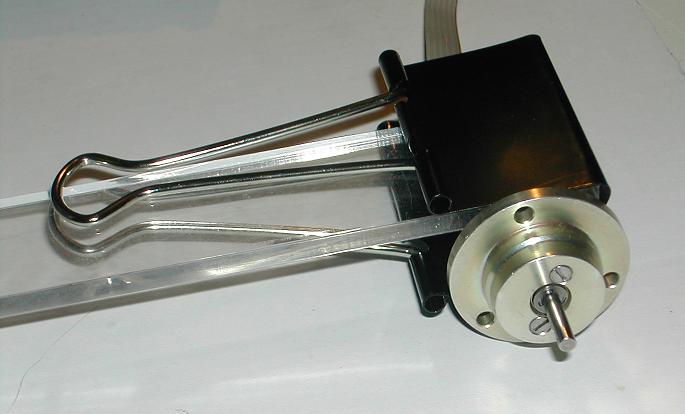
- Finished mechanics using only 3 screws. Learn to bypass
screws.
- Motor mounting with bulldog clip, fast easy, flexible.
lets not waste time machining stuff we don't need to..
The Motor driver
- H-bridge motor controller, small, simple.
- Board can fit on back of small motors


The Power supply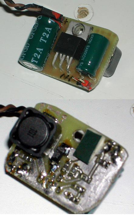
- 4 x 1.5V AA batteries = 5.2 to 6 volts working range.
- 12 volts out from 5 to 6 volts in using boost regulator.
- UC2577 boost regulator simple solution.
- Press'n peel board (one afternoon)
- Mark both male and female connectors with nail polish so
polarity is maintained.
- Nail polish stops smoke leaks.
The Microprocessors
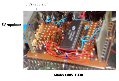 2 x Silabs 8051 variant 25 mips,
C8051F330
2 x Silabs 8051 variant 25 mips,
C8051F330
- Serial for coms between micros
- Keil compiler (fast floating point)
- 5 volt and 3.3 volt power-supply
- Wire wrap is fast, easy to change configuration.
- SIP and vero (strip) board = fast assembly
Simple Balance
- Tune motor PID control loop.
- Integral limit added to aviod integrator wind up.
(saturation)
- Add IMU when confident with performance.
The Inertial
Measurment Unit (IMU).
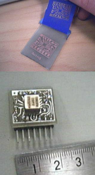 Analog devices
Gyroscope - ADXRS300 32 pin BGA
Analog devices
Gyroscope - ADXRS300 32 pin BGA
- Analog devices 2 axis accelerometer - ADXL202
- 2 boards SIP design. Press'N'Peel board.
- BGA soldered in $50 toaster oven.
- Gyroscope = high frequency rate of rotation (relative)
- Accelerometer = low frequency gravity vector (absolute)
The Kalman Filter.
- Kalman filter removes gyro DC bias and drift..
- Kalman filter low pass filters accelerometer.
- Kalman filter fuses high frequency and low frequncy
signals to give absolute gravity vector.
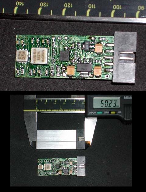
Version 2 of the
Inertial Measurement unit.
- For future projects, I2C, serial support
- Very small 50x20x9mm, Kalman filter built in.
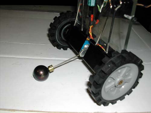
Final touches
 Added a hat to stop it smashing
into the floor when it falls over. (Kids toy ball)
Added a hat to stop it smashing
into the floor when it falls over. (Kids toy ball)
- Turn off the motors when fallen.
- Video of the pendulum balancing. Yes, it is programmed to
turn in circles.
Conclusion
- The inverted pendulum in its simplest form proves to be a
challenge. While it did balance many improvements could
be made.
- A radio control for testing purposes
- A way to get back up after falling over.
- Motor/wheel encoders for more stable control.
- "Smart" closed loop motors each with their own
processor and PID control loop.
- Smart motors can then be used in other projects.
- Motors and IMU set up as I2C slave devices with one
master microprocessor.
- I2C has only 4 wires. 5V, 0V, Clock, Data. Tidy design
with a daisy chain cable.
- Autonomous operation via sensors.
Questions ?